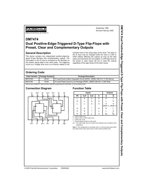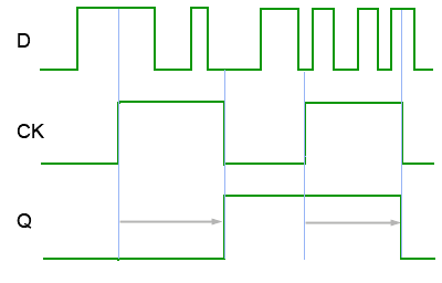

In positive edge triggered flip flops the clock samples the input line at the positive edge (rising edge or leading edge) of the clock pulse. A circuit clocked by the leading edge, as in Figure 1 (b) is referred to as being positive edge triggered while another circuit triggering on the trailing edge, as in Figure 1(c) is negative edge triggered.

Some flip flop are other logic units are triggered when the clock reaches prescribed voltage levels or goes from one voltage level to another usually without regard to voltage rise or fall time. The particular flip flop specifications will provide this information as we shall see.

Some flip flop circuits are triggered by the clock leading edge while other units are triggered on the clock trailing edge. Figure 1: Clock Waveformįigure 1: Clock Waveform (a) Full Clock Pulse (b) Leading edge (c) Trailing edge For positive logic operation we define the low to high transition as the leading edge of the clock signal (Figure 1(b)) while the transition from high to low is called the clock trailing edge (Figure 1(c)). A clock signal as seen in Figure 1(a) has two transitions, one from low to high level the other from high to low level. The pulse goes from a low level 0 volt, the positive logical 0 condition, to a high level ( +5 volts, the positive logic logical 1 condition going between the two logic levels at a fixed frequency rate. A clock pulse used to operate a flip flop is illustrated in Figure 1(a).


 0 kommentar(er)
